Table Of Content
- Most commonly used UML diagrams
- UML and data modeling
- 7. Interaction Overview Diagram
- With SmartDraw, You Can Create Many Different Types of Diagrams, Charts, and Visuals
- Get More State Chart Diagram Examples >>
- What is a UML diagram?
- NEWS & ARTICLES
- Business process modeling notation (BPMN): Everything you need to know
This diagram describes the types of objects in the system and various kinds of static relationships which exist between them. We use composite structure diagrams to represent the internal structure of a class and its interaction points with other parts of the system. UML is used to create static structure diagrams based on a variety of engineering practices that have proven to be successful in the creation of complex systems. A single class diagram describes a specific aspect of the system and the collection of class diagrams represents the whole system. Basically the class diagram represents the static view of a system. Activity diagrams show the procedural flow of control between class objects, along with organizational processes like business workflows.
State-of-the-Art UMass Lowell Aerospace Center Seeded by $5.5M Grant - UMass Lowell
State-of-the-Art UMass Lowell Aerospace Center Seeded by $5.5M Grant.
Posted: Wed, 16 Aug 2023 07:00:00 GMT [source]
Most commonly used UML diagrams
Component diagrams are a special kind of UML diagram to describe the static implementation view of a system. Component diagrams consist of physical components like libraries, files, folders, etc. So there are two Instance Specifications for the two attachment objects to be uploaded. Activity diagrams have symbols for activities, states, including separate symbols for an initial state and a final state.
UML and data modeling

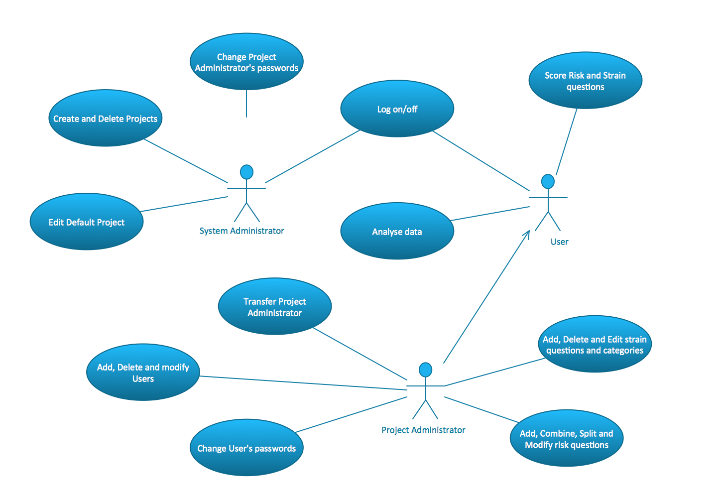
Sequence diagrams — sometimes known as event diagrams — show the order in which your objects interact. This includes the lifelines of your objects, the processes that interact with your objects, and the messages exchanged between the objects to perform a function. A use case diagram is often used as a top-level overview of how users and systems interact. As a result, it’s a useful way for a non-technical audience — which can include key stakeholders — to visualize your system. Most commonly, a UML diagram is used to analyze existing software, model new software, and plan software development and prioritization.
7. Interaction Overview Diagram
It describes the working of both the software and hardware systems. They can be used to describe the business workflow or the operational workflow of any component in a system. Sometimes activity diagrams are used as an alternative to State machine diagrams. Check out this wiki article to learn about symbols and usage of activity diagrams.
UMass Lowell Art and Design Professor Wins Prestigious Pollock-Krasner Foundation Award - UMass Lowell
UMass Lowell Art and Design Professor Wins Prestigious Pollock-Krasner Foundation Award.
Posted: Mon, 21 Aug 2023 07:00:00 GMT [source]
However, the Book class does not depend on the Person class; it can exist independently and does not rely on the Person class for its functionality. In the example of bank accounts, we can use generalization to represent different types of accounts such as current accounts, savings accounts, and credit accounts. Composition is a stronger form of aggregation, indicating a more significant ownership or dependency relationship. In composition, the part class cannot exist independently of the whole class.
Similar to flow charts, these diagrams plot out a system’s business or process flows—for example, payment, registration, and travel booking flows. Deployment Diagram Deployment diagrams depict the physical resources in a system, including nodes, components, and connections. UML 2.0 helped extend the original UML specification to cover a wider portion of software development efforts including agile practices. It is important to distinguish between the UML model and the set of diagrams of a system.
The process isn’t moving your workflow along as quickly as you’d hoped. To identify what’s causing the holdup, you refer back to your UML diagram and pinpoint the root of the problem. When it comes to creating a UML diagram, a lot of businesses use a UML diagram template. The best way to understand UML is to look at some examples of UML diagrams. A complex enterprise application with many collaborators will require a solid foundation of planning and clear, concise communication among team members as the project progresses.
NEWS & ARTICLES
In this article, we’ll outline what UML is, how to use a UML diagram, and the different types of UML diagrams out there. So whether you’re a business manager or a software developer, an understanding of UML diagrams can go a long way. It’s always helpful to refresh your memory and familiarize yourself with the best practices for UML diagramming.
Business process modeling notation (BPMN): Everything you need to know
An Interaction Overview Diagram models a sequence of actions and helps us simplify complex interactions into simpler occurrences. As the UML is a modeling language used to model software as well as non-software systems, but here it focuses on modeling OO software applications. It is essential to understand the relation between the OO design and UML.
While activity diagrams show a sequence of processes, Interaction overview diagrams show a sequence of interaction diagrams. State machine diagrams are similar to activity diagrams, although notations and usage change a bit. They are sometimes known as state diagrams or state chart diagrams as well. These are very useful to describe the behavior of objects that act differently according to the state they are in at the moment. The State machine diagram below shows the basic states and actions.
In fact, UML diagrams are used widely across different areas of business. This is how you demonstrate software deployment across hardware components. Your deployment diagram could show hardware such as a client server, database server, and an individual PC, with collaboration software layered on top of it. The Interaction Overview Diagram focuses on the overview of the flow of control of the interactions. It is a variant of the Activity Diagram where the nodes are the interactions or interaction occurrences. The Interaction Overview Diagram describes the interactions where messages and lifelines are hidden.
While the process of creating one differs greatly depending on your business needs, we’ll outline a couple of the best practices you can follow. Now that you know about the different types, you’re probably wondering how to make a UML diagram. You can see from the diagram that the main focus lies with how and where the different objects are connected.
It has the same notation rules, but it’s more specialized and tailored to a complex system. The second and third sections provide details about class operations, behaviors, and attributes. There are various types of UML diagrams that are used for different software structures. There are 14 official types, with some additional versions that aren’t officially recognized but are widely used. Capture a system’s components in various states, as they respond to external and internal influences.